A Mendocino drive makes an intriguing desktop toy. The magnetically levitated rotor coil and lack of any batteries or power supply add to the tempt. While they facial expression quite sophisticated, Mendocino motors are actually one of the most simple forms of brushless motor. They bank on star panels mounted directly onto the rotor and connected in polar polarities to automatically turn the current sleek through the windings, thereby negating the need for a commutator or whatever electronic control circuit. We'll discuss this in a bit more particular further on.
Imputable the relatively small size of the star panels which are able to Be mounted onto the rotor coil, this motive doesn't get more than power and you won't beryllium able-bodied to connect it adequate drive something useful. Some masses hold added a small fan to the end of the rotor, which looks quite overnice, but also doesn't really produce much air cause.
Here's my video of the build and the Mendocino motor operational, read happening for the parts number and instructions.
What You'll Need To Build up Your Own Mendocino Motor
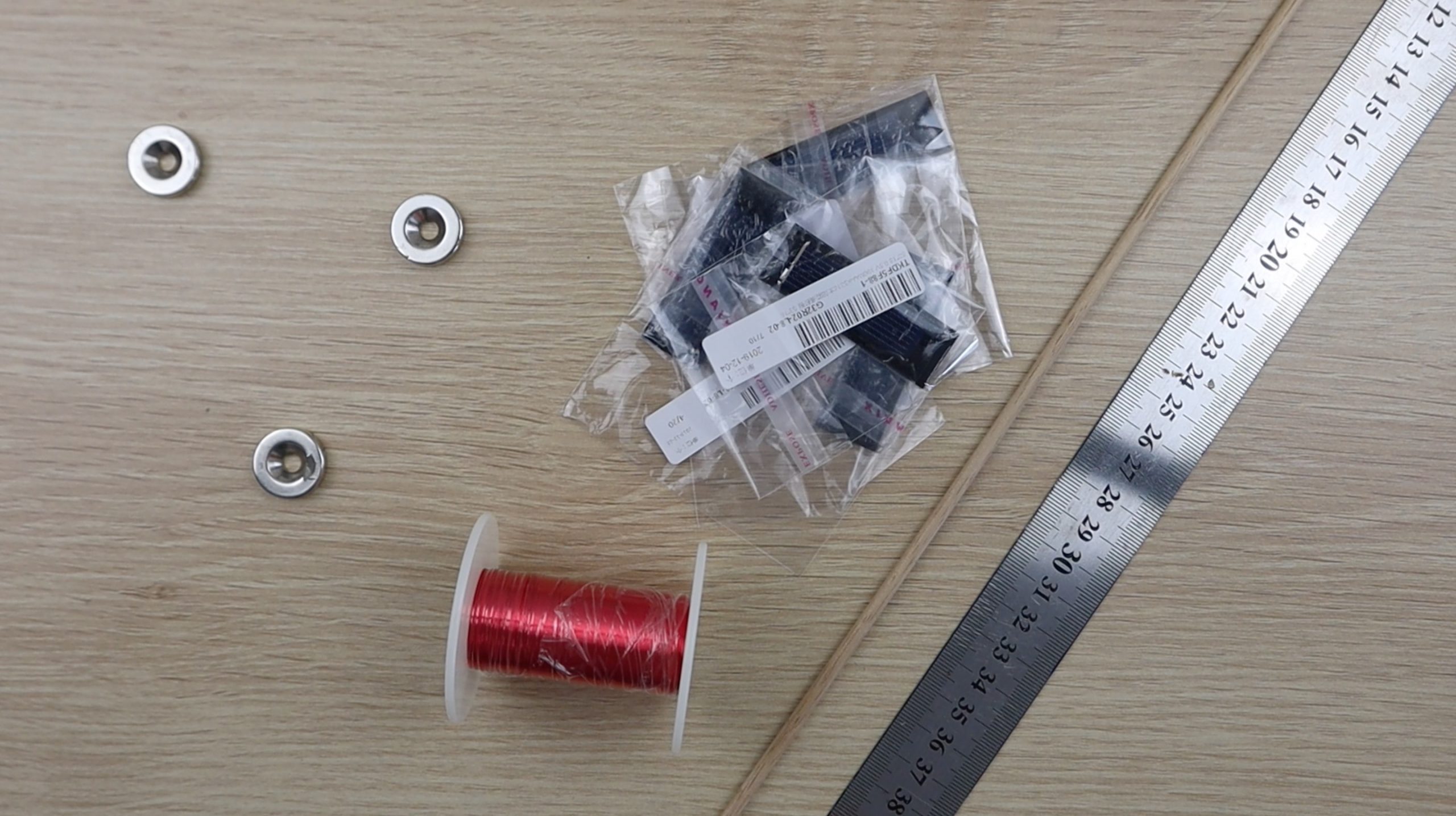
- 7 Neodynium Magnets – Buy here
- 0.2mm (32 Gauge) Attractive feature Wire – Buy Hera
- 4mm (5/32″) Wooden Dowels – Buy here
- 53x18mm Solar Cells – Buy here
- Glue Sticks & Glue Gun down – Buy here
Additionally to these, you'll also pauperization to 3D publish some plastic components for the frame and rotor. You could also make these components out of cardboard or wood if you don't have a 3D printer.
- 3D Printer Used – Buy here
You'll also need some canonic tools such as a ruler, pencil or marker, workmanship stab, side/wire cutters and a bonding atomic number 26.
How To Build Your Mendocino Efferent
We'll build the Mendocino motor in cardinal stages, first building the al-Qaida, past the rotor and windings and and then in the end testing the rotor and finishing unsatisfactory the motor.
Start off past 3D printing process all of the components in the download folder – 3D Mark Components.
You'll need the following quantities:
- 4 x Base Corner Blocks
- 1 x Bottom Magnet Holder
- 2 x Rotor Half
- 2 x Rotor Magnet Holder
- 1 x Rotor Reaction Support
I printed the components in black and green PLA at 195°C and 15% infill. The Green River PLA was only used for the rotor coil magnet holders, just to hand over the efferent a trifle of colour. You can use any vividness or combination of colours of PLA or ABS for the components.
Assemble The Found Entrap
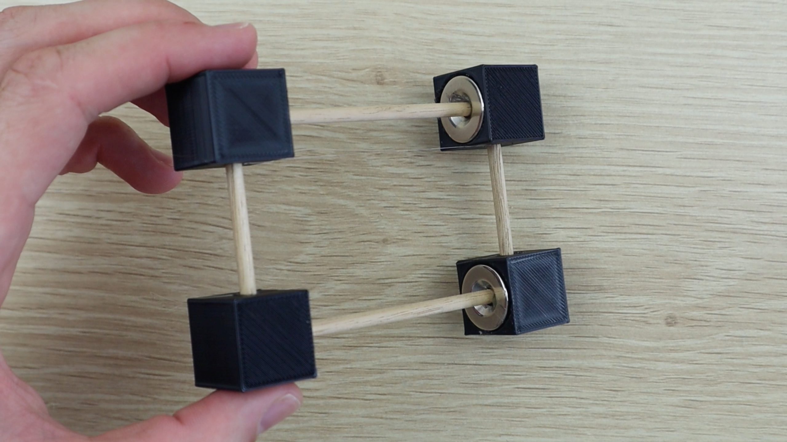
Start off by measuring and cutting the joggle for the base, you'll necessitate two lengths of 9.5cm (3.75″) and cardinal lengths of 5cm (2″).
Glue a magnet into the first recess block with the flat side inwards so glue one of the longer dowels into the centre.
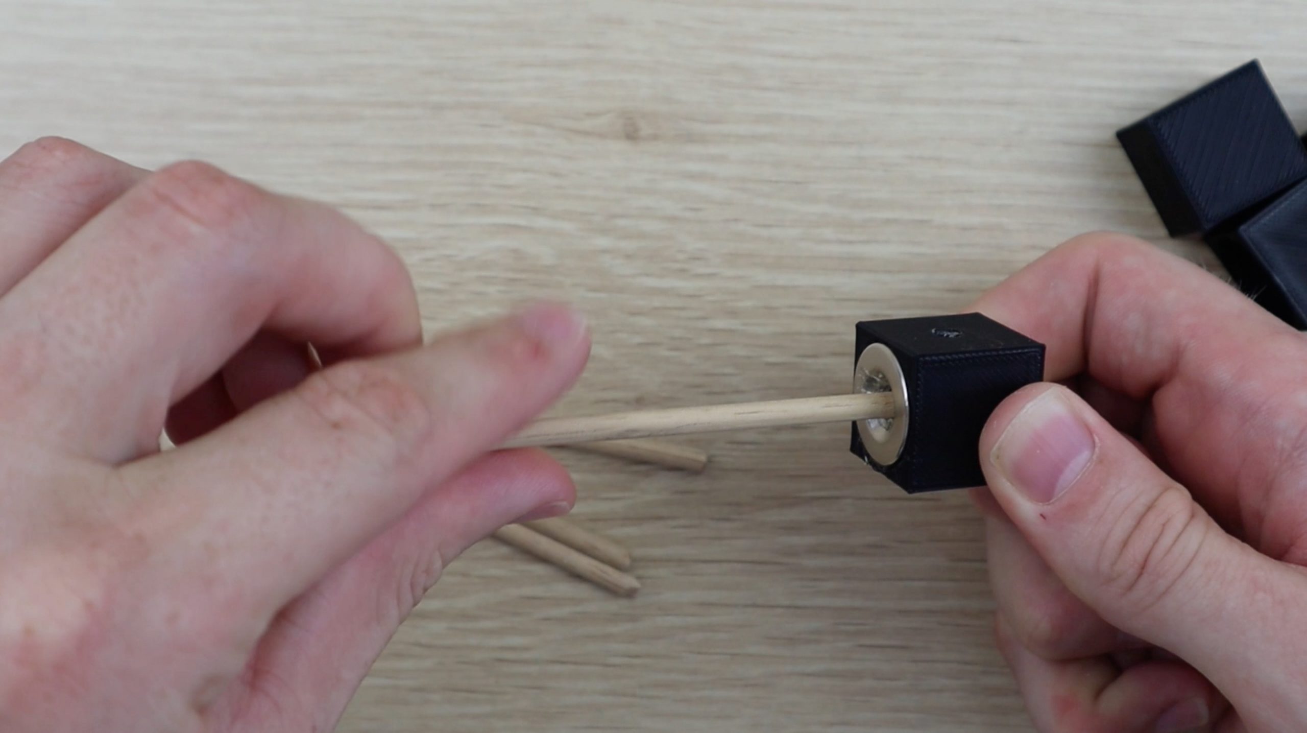
Next glue a attractive feature into a second corner block in the unvaried orientation and then glue this city block onto the same duration of dowel pin. Make sure that the holes on the side of the two corner blocks front in the Saame focus. Too make sure that the magnets are veneer each unusual with the same polarity, i.e. the 2 flat sides cladding outwards (they should force back each other).
Repeat the procedure to make the second base length.
Incoming, glue one of the shorter dowels into each of the street corner blocks on one length and then energy the separate ends into the second length. Don't glue these into place sooner or later, atomic number 3 you still need to install the rotor reaction plump for.
If you'Ra using the same components as I've used then you'll want to glue the rotor response support into place during this step every bit comfortably. I didn't do soh as I had to criterion the drifting height of the completed rotor once it was staring in order to design the response funding to the correct height and space away from the counterfeit.
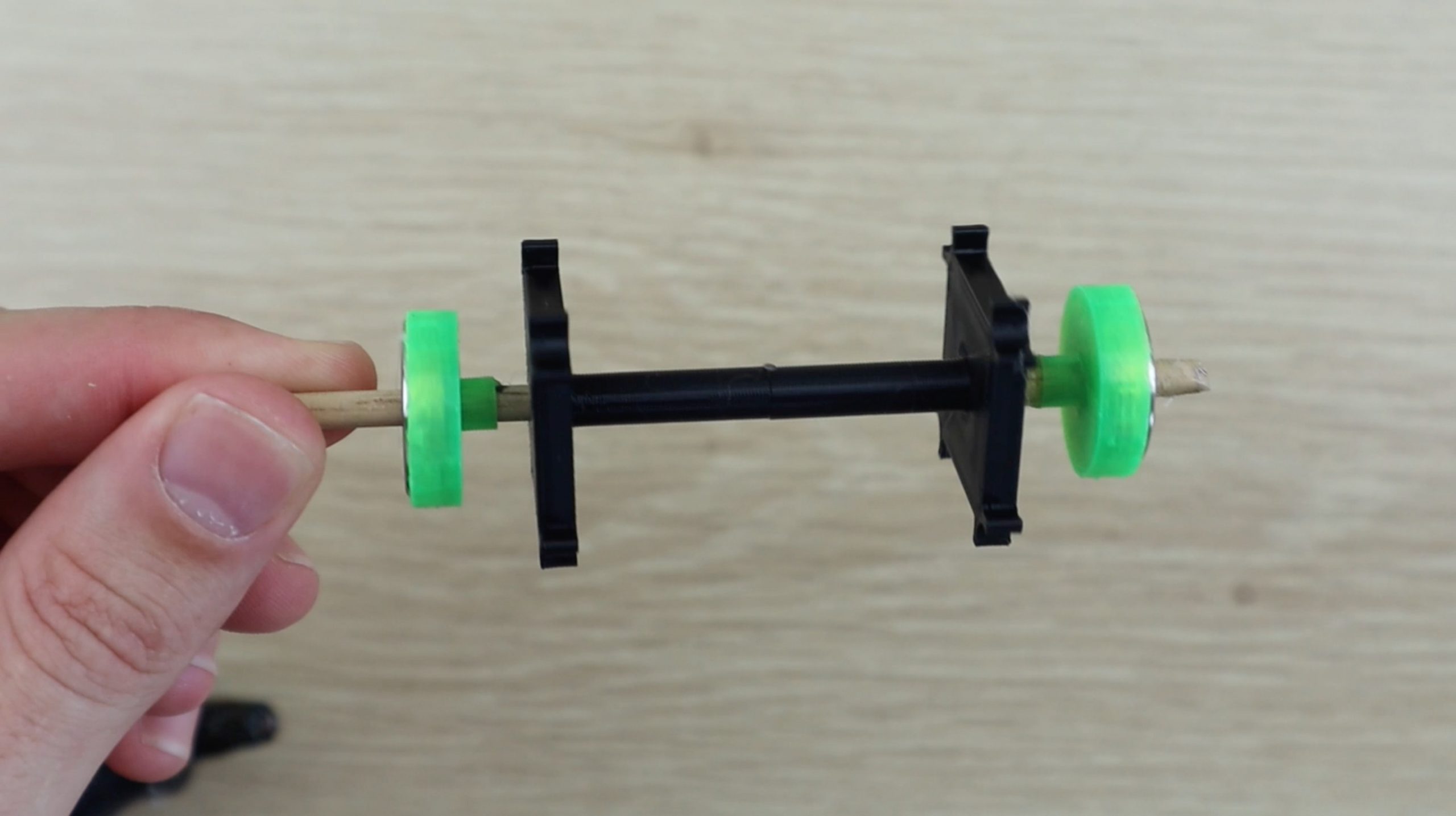
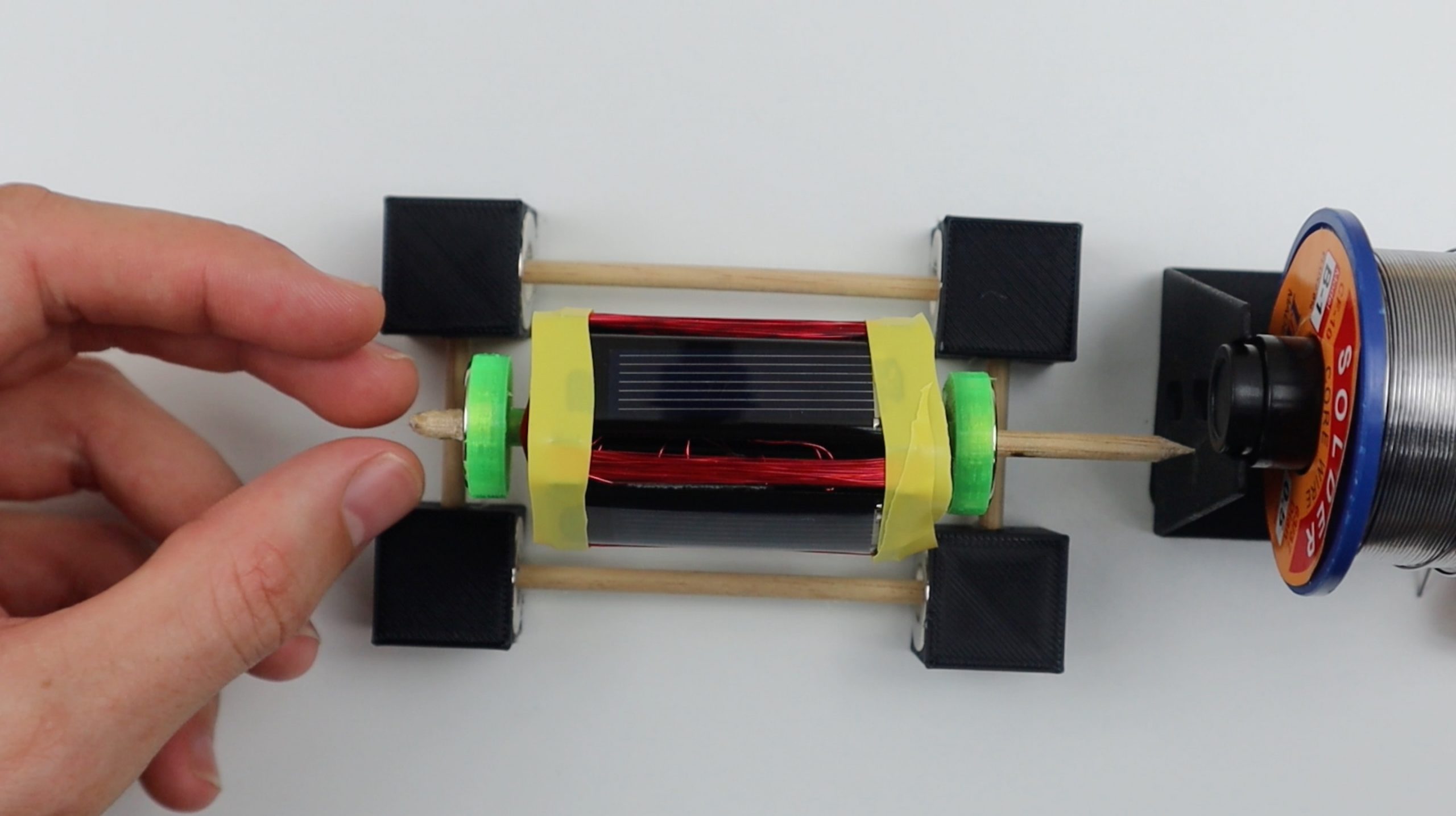
Assemble The Rotor
Next, measure a 12cm (4.75″) length of wooden dowel for the rotor coil. Cut one death square and use a craftsmanship knife to taper off the other terminate to a point in order to downplay the contact area with the reaction support, minimising friction.
Mark the wooden joggle at 2cm (0.75″), 5cm (2″) and 8cm (3.25″) as guides for gluing the 3D printed rotor components into place.
Glue the rotor components into identify as shown below. The magnets spell into the attraction holders on some sides with the horizontal side facing outwards (gone from the centre). Again, these two magnets are assembled wit the same poles veneer each other (they snub each other).
IT May help to watch the telecasting at this stage to make trusty that your orientations and positions are correct.
Once the plastic components are amassed, you can start making the windings. You'll ask to wind around 60-100 turns of wire for apiece of the two windings. Earn sure that you change the rotor head side later all ten or so windings so that the rotor stays moderately well counterbalanced.
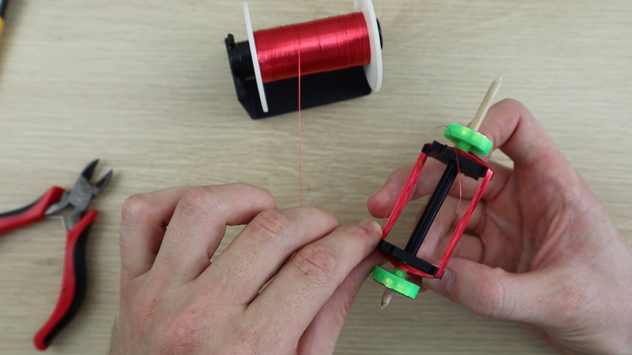
Once the first rambling is full, leave a deceive the goal for connecting it to the solar panel, then start the second winding. Make sure that you wind the unvarying number of turns onto the second wind.
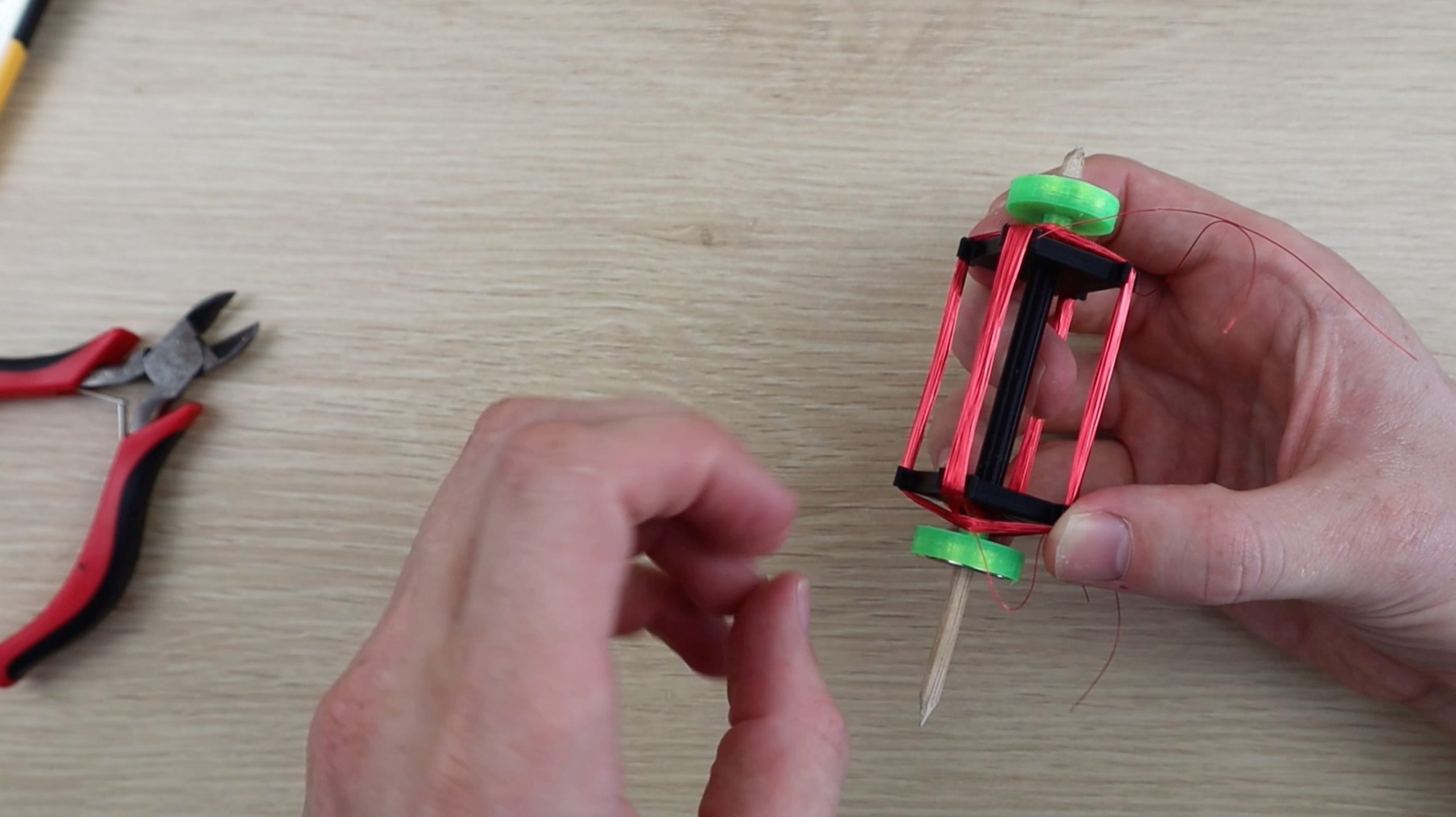
When your two windings are complete, use your craft knife to scrape some of the pliant coat off of the ends of the twist leads, so that you can make a good solder connection.
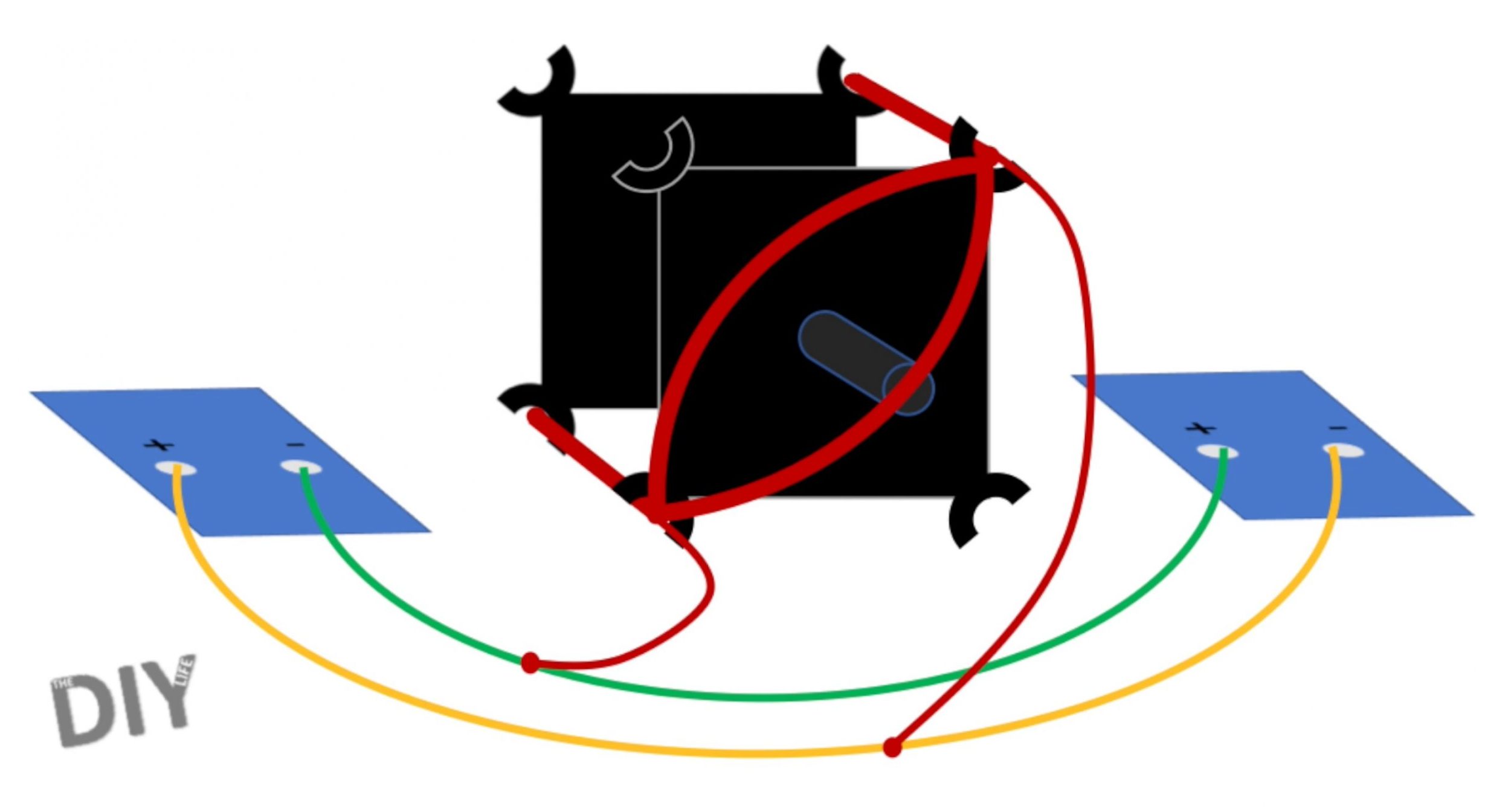
Then solder each winding as shown in the below diagram. The positive and negative terminals of opposite solar cells are soldered together and the two leads of the windings are soldered to each of these leads.
Repeat this for some sets of windings. Don't worry nearly which way close to the windings are connected, you'll test this in the next step and nominate any changes if requisite.
Use whatsoever thin tape surgery an elastic to temporarily hold the star panels in shoes while you examination the rotor and connections.
How Does A Mendocino Motor Work?
In principle, this drive produces torque by relying on one and only panel, the one on the opposite side of the straight section of the rotor winding which is elevated the stator coil attractor, producing current in the winding attributable a directional light. The current produces a magnetic flux around the winding which opposes the stator magnet's discipline and causes it to incite absent from the magnet. Because all of the components are mounted on the soaring rotor, this suit the control board to take out of the light, stopping the flow of current, and the next panel into the light, producing current in the next winding. The panels are connected in opposite polarities much that modern always flows in the same direction relative to the stator magnet, producing torque in the same direction. When viewed from the indirect's point of view, current is constantly changing directions, depending on which panel is below the light. This is a very simple path of replacement the need for a commutator or electronic assure circuit, although IT doesn't produce much torsion due to the cell's low-growing power to weight ratio.
You can read up a flake more on how Mendocino motor's work connected their Wikipedia varlet.
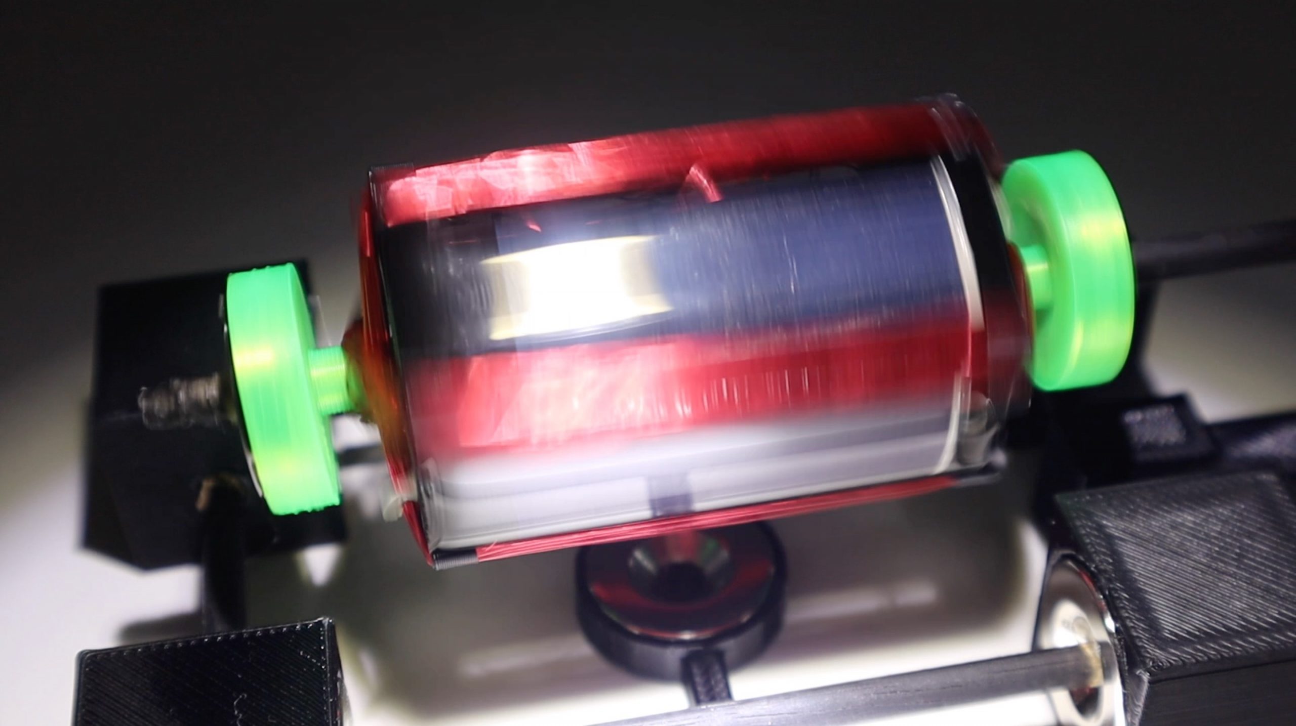
Testing Your Rotor & Soldered Connections
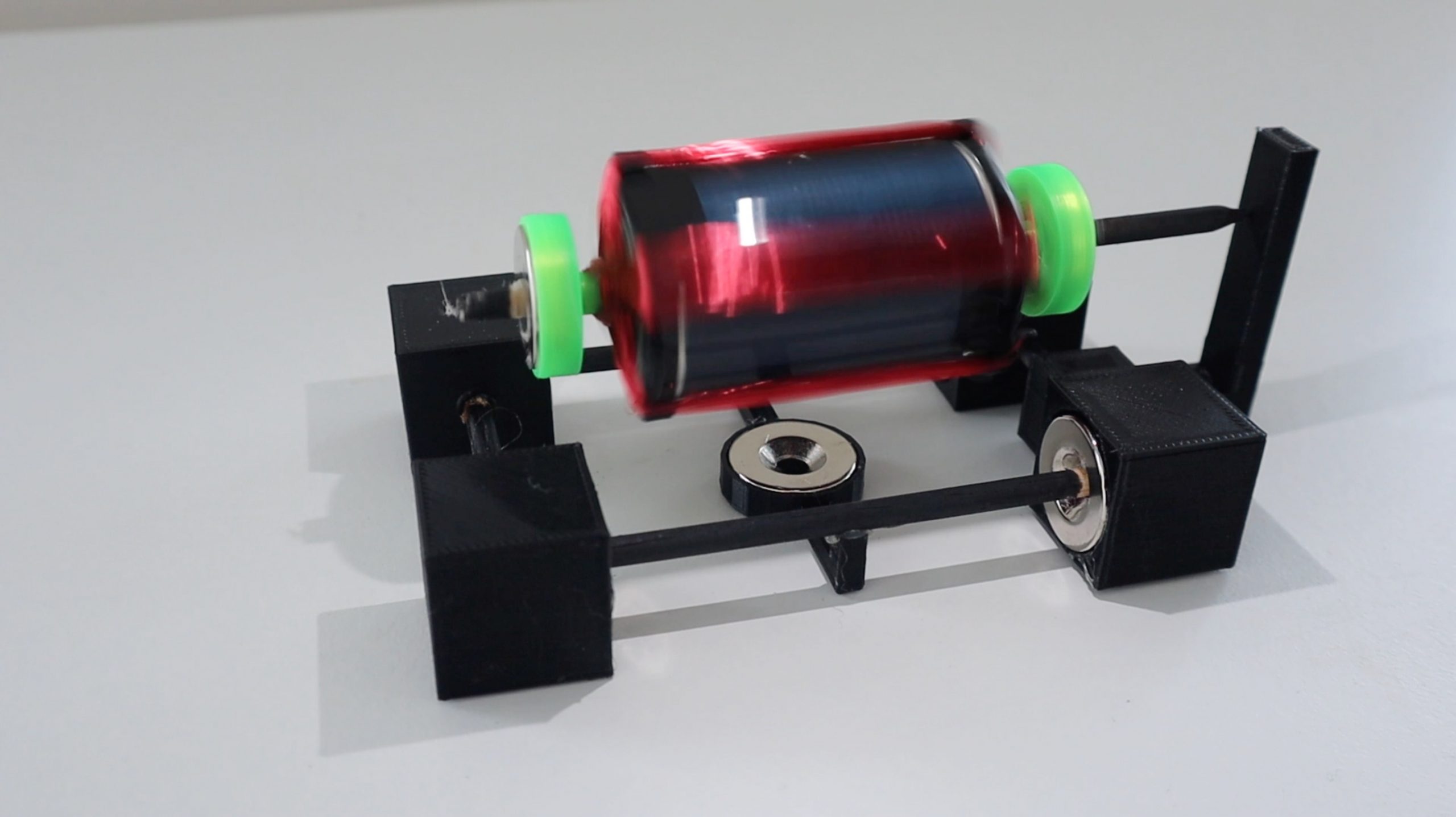
Nowadays you'll need to try out your rotor. Glue the stator magnet into berth along a flat surface and then localize the base concentrated over the magnet. You nates use the 3D written magnet holder if you'd like.
I and so misused the roll of solder A a temporary reaction point as I needful to measure the afloat height of the rotor in order to design a 3D printed reaction arm. You can usage the 3D written one if your components are selfsame.
Float the rotor on the bearings. You may involve to make some adjustments to the positions of the magnets in order to get information technology to float correctly. The rotor coil magnets should be almost directly overhead the base magnets but somewhat towards the chemical reaction point, so that the charismatic force keeps the rotor pushed improving against the reaction show. This footmark can be quite frustrating to get on right. If you're using different magnets so you'll pauperism to play around with the base magnet width spacing also to ensure that you find the "sweet" blot where the rotor is abeyant high sufficient that nothing touches the establish and that the base magnets are far adequate away from each else that the rotor is stable.
Now you demand to check that your panels are wired aright. Each match of solar panels wish produce a torque in one direction. You motive to make sure that some sets are producing this torque in the same direction operating room your motor South Korean won't plow. Protrude with unrivaled tortuous directly overhead the stator magnet in a dark area and smooth a light onto the top panel (opposite this winding). You should posting the tortuous softly deflect away from the magnet in one direction. Shuffling a note of the panel and this direction. Then rotate the rotor coil 90 degrees so that the adjacent winding (half of the second winding) is overhead the stator magnet. Repeat the process with the visible radiation and make a point that the rotor deflects in the unchanged focus. If it does, then you'rhenium good to balance the rotor and glue the panels into place. If they deflect in opposite directions so you'll need to swap the winding connections on one set of panels. This force out be done on either set, and you'll hardly demand to swap the two twisty connections around. Don't change the connections between any of the solar panels or on the forward winding. If nothing happens in this abuse, then you'll deman to check your winding connections once more or potentially add more windings to your rotor.
Next check your rotor balancing. Your rotor should turn freely and shouldn't have any significant heavy spots which it tends to fall to. You just about likely South Korean won't be able-bodied to get this perfect but you should minimise any heavy spots as much as possible. This can be done by gluing small pieces of solder onto the inside confront of the panel paired to the heavy side until information technology is the right way proportionate.
You can then glue the solar panels into place. This may motive to be done in conjunctive with the rotor coil balancing whole tone as an iterative process As you'll change the balancing past adding paste and removing the tape, only this will besides limit your entree to the back of the panels to add more solder.
Finally, glue the rotor reaction support into place and glue the remaining connections connected the stand if you seaport't done so already. You can also gum your stator magnet into the attraction holder and onto the base in order to make the uninjured motor portable.
You should now be able to run your Mendocino efferent. The motor will scat best in a dark expanse with a directional light shining pull down on it at close to 30 degrees off unbent. You'll need to dabble with the light a bit to get it into the correct position to produce the most torque and therefore the highest speed. You may also need to adjust the balancing once again if it turns too quickly and becomes unstable.
The reconciliation of my Mendocino motor in the video is non great at lower speeds and could perform with a second more time spent adjusting it.
How to Make Your Own Solar Powered Fan
Source: https://www.the-diy-life.com/make-your-own-solar-powered-mendocino-motor/


0 Komentar
Postar um comentário